9.6 KiB
Audio Visualization for less than $10!
TODO: introduction
TODO: Block diagram
Input signal: "Line level"
First, let’s get a view of the signal we are accepting on the circuit’s input.
Magnitude
With some variation, it's common knowledge (by means of human experience) that most devices which accept a set of headphones through a 3.5mm "TRS" audio jack will output roughly the same maximum volume through that set of headphones.
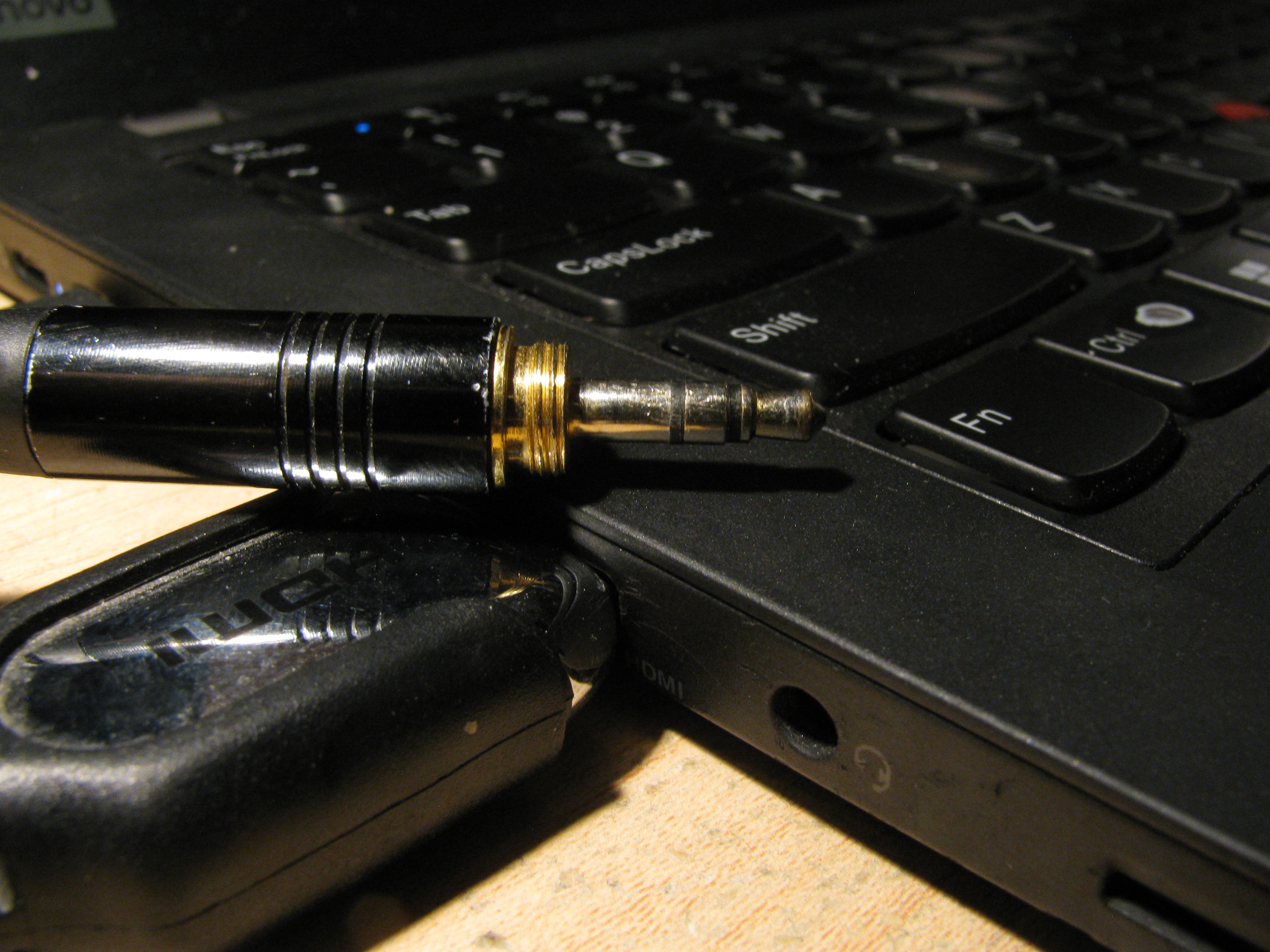 |
|---|
| A typical, well-loved 3.5mm TRS jack besides a laptop line-out port. |
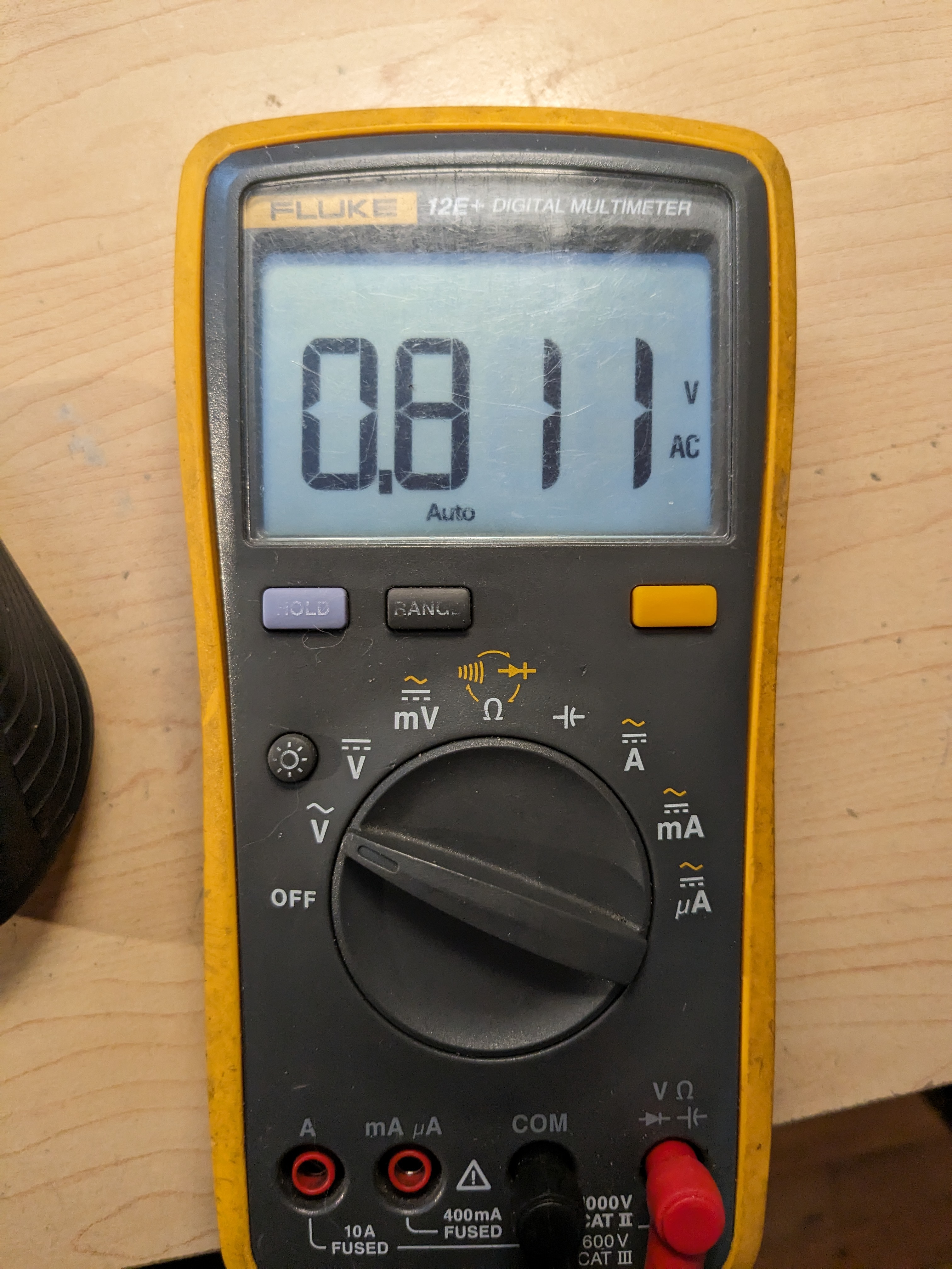
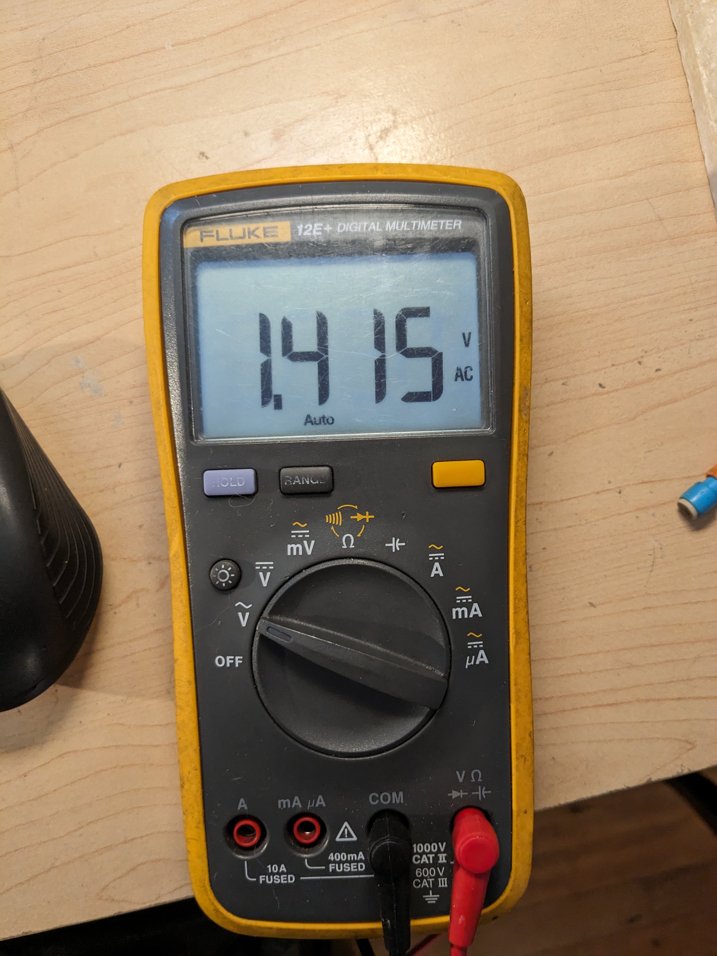
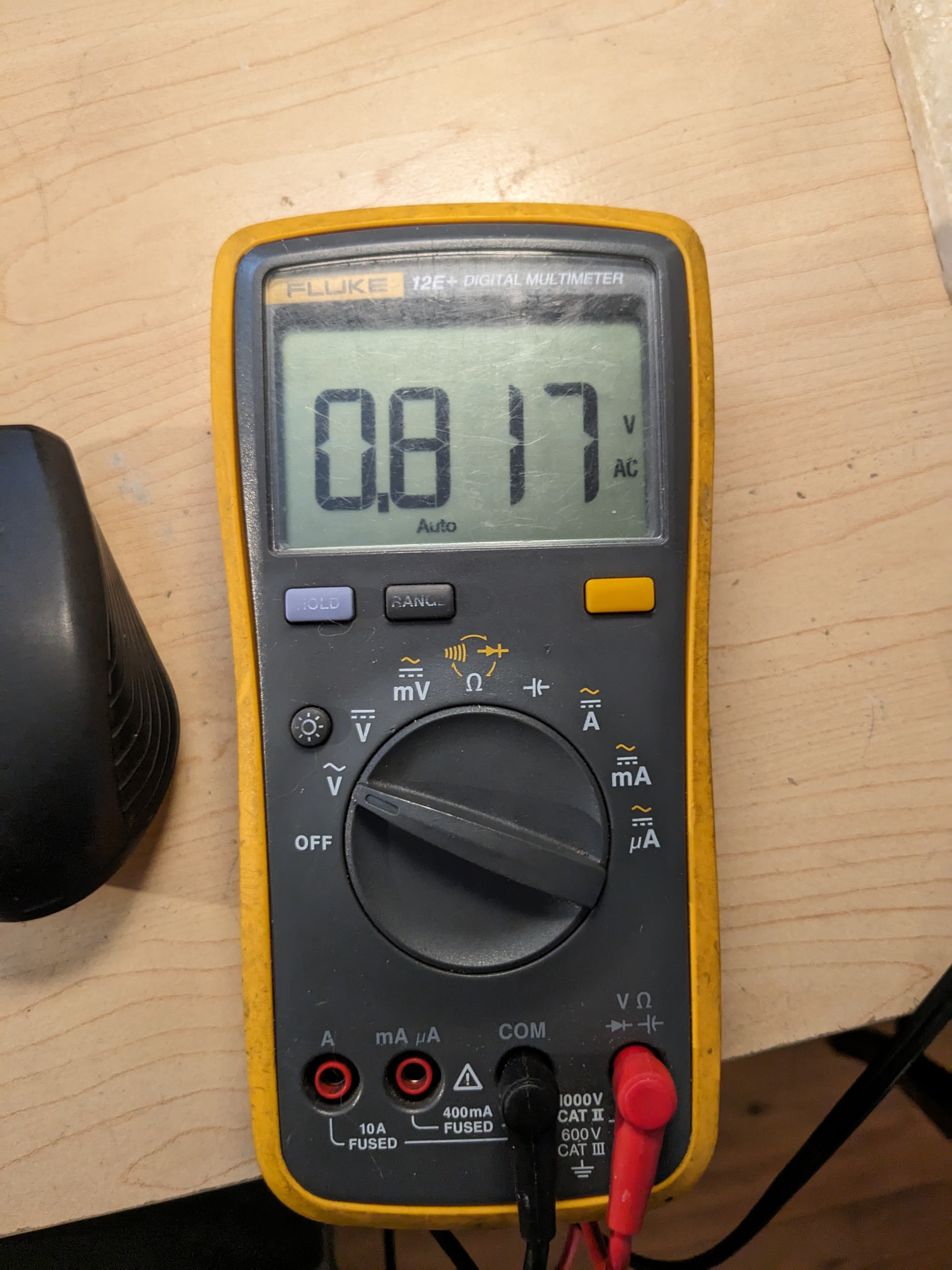
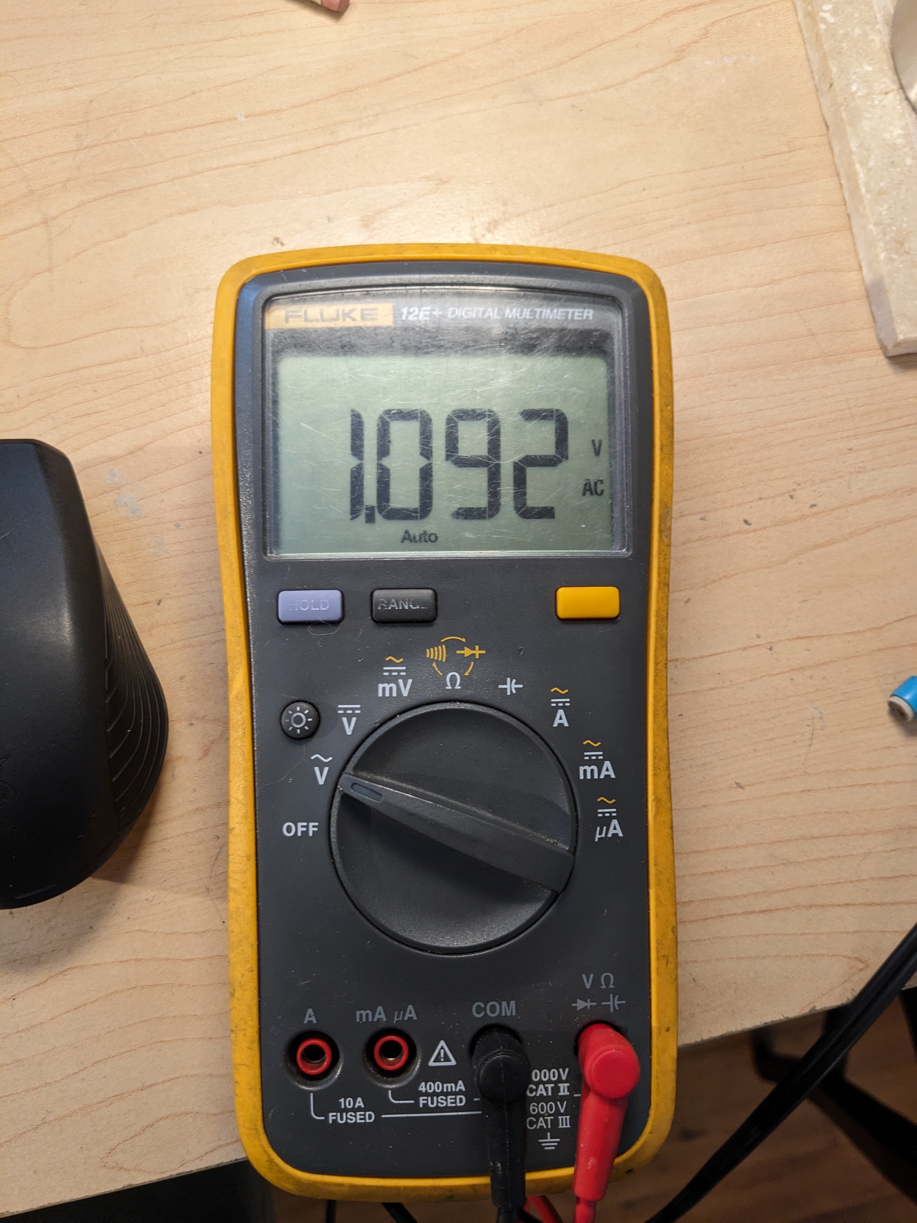
Don't believe me? Grab a 3.5mm cable meant to connect an output, like a phone, to a speaker, and use a multimeter to measure the unloaded RMS AC output voltage of a 60Hz tone. Be sure to use the same software on multiple devices to get a normalized comparison of different hardware.
 |
|---|
| We generated this 60Hz tone using Audacity, under Generate > Tone > Sine, 60 Hz, Amplitude 1 (100%) |
-
Experiment pitfalls:
-
Q: Uhh ... which conductors am I measuring?
If you're unsure which conductors to measure between: the sleeve is usually a common reference ground, but in doubt, use your multimeter in continuity mode and see if you can find contuinty to the computer case or, for example, the outer shield of a USB connector. -
Q: Why 60Hz?
Not all multimeters are equal, but some things don't change: any portable multimeter equipped to probe the 60Hz, 120VAC signal provided by your household electrical socket is also suited to calculate RMS AC voltages for 60Hz sinusoidal signals. The Asian-market Fluke 12E+ used here was able to measure the highest frequencies our sound cards could produce -- around 20 kHz -- but a cheaper Centech multimeter struggled past a perfectly audible 1 kHz tone.
-
-
We tried this experiment on a Thinkpad and a Dell desktop, using the
mpvmedia player on two Fedora Workstation systems:
 |
 |
 |
 |
|---|---|---|---|
| Laptop, 100% | Laptop, 130% | Desktop, 100% | Desktop, 130% |
The signal was identical at 100% volume on each system ... but when we
asked mpv to overamplify the volume to "130%", the laptop and
desktop began to deviate.
Frequencies
Depending on what type of music you listen to, you'll find that the frequencies that are most pronounced vary widely. If you already have a piece of audio in mind that you want to visualize using your board, you can use this neat online tool published by Academo to find some frequencies at which the audio peaks.
I've already made my choice, of course. Folks who grew up with a first-generation PlayStation (or who had older siblings who did, in my case) might find my online handle oddly familiar -- as a kid, I always liked watching the rain, so when I encontered the stormy puzzle-platform level Hurricos in my first playthrough of Insomniac's Spyro 2: Ripto's Rage, I felt right at home.
 |
|---|
| Concept art for Hurricos, produced by John Loren for the Spyro: Reigited Trilogy. |
The soundtrack for this level shows pronounced frequencies around
G_2 and G_4; as it continues, the composer Stuart Copeland (yes,
that Copeland)
integrates some sort of electric arc sound effect reminiscent of
either a hi-hat or a brush-slapped snare -- the tone centers around
G_8.
 |
|---|
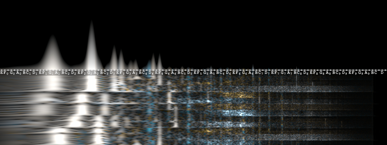
Hurricos, as seen by a custom mpv visualizer |
Converting those notes back from
A440 under
12-tone equal
temperment into
Hz is easy. If you count the number of downward keyboard half-steps
n from your note down to A_4, your frequency in Hertz will be
f_{\text{Hz}} = 440 \times 2^{\left(\frac{n}{12}\right)}
For example, G_2 = 440 \times 2^{\left(\frac{-26}{12}\right)} \approx 98 \ \text{Hz}.
Pitfalls
-
How precise should I be with measuring?
Because you are going to be constructing filters with discrete components whose values cannot be finely controlled, don't fret about the difference between 800 and 830 Hz. (Get it? Fret?)
Our values
| A440, note | Frequency, Hz | Frequency, rad./s |
|---|---|---|
G_2 |
98 | 616 |
G_4 |
392 | 2463 |
G_8 |
5588 | 35108 |
Let's make it glow!
The circuit design we are using is very simple: first, pre-amplify the signal; then, reduce parts of it using band-pass filters. This design can be extended further if you would like to add more LEDs for different frequencies.
Attributes of amplifiers
All amplifier circuits are active by nature; without an active addition of some sort, you cannot increase the magnitude of a signal.
In this design, we will feed our line-out audio signal into an amplifier -- we selected an inverting amplifier, but a non-inverting amplifier works fine as well, since audio signals can be driven either way. The circuit consist of two resistors and an op-amp.
 |
|---|
| The inverting amplifier circuit in KiCAD, with values for R1 and R2 already selected |
Amplifier circuits produce a gain - they multiply the input signal. In some cases, the gain is a function of the signal's frequency, but in our case, outside of frequencies too high or too low to hear, our gain is not frequency-dependent: the gain is flatly the negative of the ratio of our resistor values, or $-\frac{R_2}{R_1} = -\frac{2.4k}{470} \approx -5.1$.
Why this formula for gain? An intuitive proof is that, connected in the circuit drawn out above, an ideal op-amp will drive its output voltage indefinitely high if the inverting input voltage is lower than zero (since the non-inverting input is linked to ground); and indefinitely low if the inverting input is higher than zero. Since R1 and R2 connect the input voltage and output voltage at the inverting input, a voltage divider between the two is set up and the ratio of the two resistances binds the ratio of the two voltages, inexorably leading to an inverting input voltage equal to the non-inverting input voltage.
We can describe the operation of our pre-amplifier with a transfer function:
H(s) = \frac{V_{out}}{V_{in}} \approx -5.1
(The value given for our transfer function is notably frequency
independent: there is no component in the expression for s.)
Most op-amps available on the market are unable to drive their outputs signal higher than their supply voltages; this is true of our selected op-amp, the TLC081.
Since we are supplying the op-amp with two 9V batteries, we can safely
say we will not be exceeding 9V. We expect to handle no higher than 1V
AC RMS = 1.41V peak on our input, so a gain of -5.1 yields a peak
voltage of \approx 7.2 V, right in range.
Note that since we started with a max V_{RMS} of about 0.8, we can
roughly expect voltage peaks of 5V.
Attributes of (passive) bandpass filters
As for our three frequency-selective filters: we only want the LEDs to light up when certain frequencies are most pronounced, so we will be using band-pass filters.
Before we move forward, I'd like to avoid a dangerous pitfall in how we review our design: our LEDs.
Wide variations in LED brightness, "forward voltage" (a convenient lie which ignores how diodes really work), peak current, the end user's taste in brightness and tolerance for a light glowing when it perhaps shouldn't -- all of these factors threaten to poison our consideration of which exact values to select for the band-pass filters that permit an output signal at different centering frequencies.
Complicated by the fact that your ideal light-up frequencies may also differ, we need to step back and recognize exactly what we care about and what our real challenges are:
Design principles, and how we'll achieve them
We want each LED to glow the most when a particular frequency swells
That means our pass-band will be centered on a particular
frequency. A pass-band filter has not only a center frequency, but a
bandwidth as well to contend with -- the difference between the
lowest and highest frequency which the filter will "permit"
(considered as the half-power, or voltage-over-\sqrt{2}) -- the
cutoff frequencies \omega_{c_1} and \omega_{c_2}.
Essentially all LEDs require at least 1mA forward to glow appreciably, and have a forward voltage of 1.5-3.6V.
So, if the impedances in our filters act to limit the available current when a given signal peaks -- remember, at +5V -- then
Transfer function
But what about the LEDs?
The transfer function A tricky problem we
Part selection
LEDs
My teacher likes the LM741. Can I use the LM741?
Literally, no. Do not use this opamp. You will suffer. It will hurt you and your family. It will not work in our circuit.
Now that I have your attention: ... this opamp is not ideal in our circuit, becuase
A few reasons:
- Insufficient slew-rate when amplifying >10kHz signals to 7V https://youtu.be/e67WiJ6IPlQ?t=566