| .. | ||
| Photos/Raw | ||
| BM60051FV-C.PDF | ||
| clarity_inverter_circuit.png | ||
| clarity_inverter_pcu_power_module.jpg | ||
| Development_of_a_new_Two-Motor_Plug-In_Hybrid_System.pdf | ||
| Development_of_Electric_Powertrain_for_CLARITY_PLUG-IN_HYBRID.pdf | ||
| Gen3_Insight_PCU_Paper.pdf | ||
| README.md | ||
| Third-Generation_Power_Control_Unit_for_Small_Hybrid_Vehicle.pdf | ||
| Transmission-Mounted_Power_Control_Unit_with_High_Power_Density_for_Two-Motor_Hybrid_System.pdf | ||
WIP
Summary
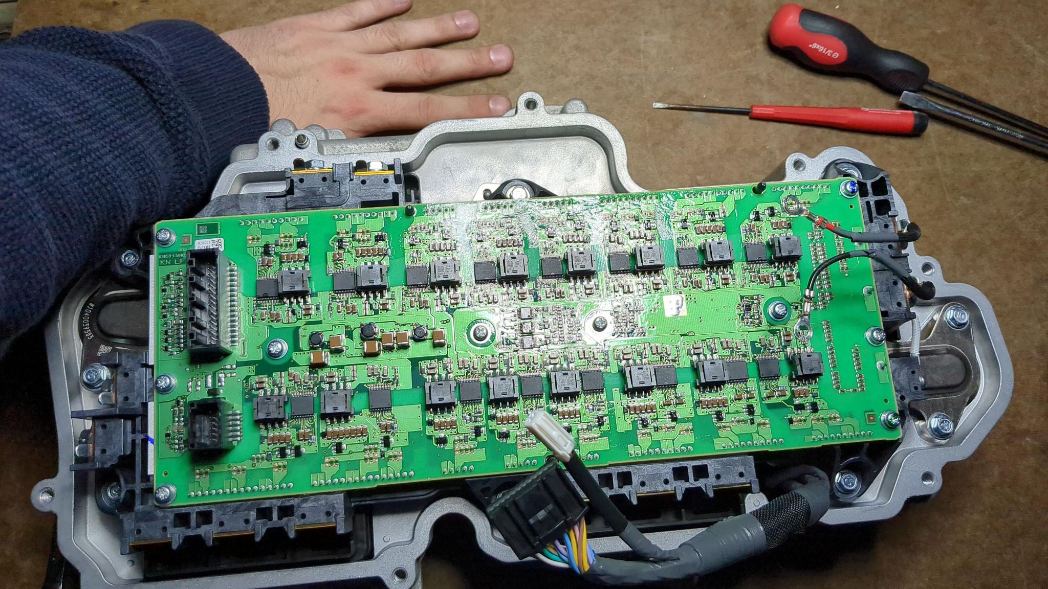
The Clarity PCU is simple. The control board is an Infineon (Cypress) ARM MCU, controlled components (so far identified) are
- QTY16 ROHM BM60051 gate drivers (see
./BM60051FV-C.PDF) - a pre-charge relay
- some temperature sensors
- a battery bus current sensor
Connections
Control Unit <=> Power Module
Control -> Power board is QTY1 32-pin cable (probably QTY2 wires per driver), QTY1 12-pin cable.
Control Unit <=> Outside world
There's a 30-pin connector wired to the other side of the control board.
Cooling
Almost all the internal space is dry, except for a cooling pipe squashed in the center. I know coolant is one-way, I just don't know which has to be cooler (the copper core or the gates?).
For prototyping, all of the components can be briefly run without coolant.